Data Collection
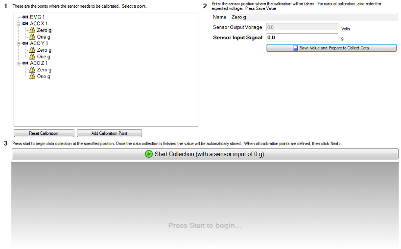
Step 1 shows the channels which need to be calibrated, and data points on each channel. Each data point is comprised of a sensor output voltage, measured by EMGworks, and the sensor input which produced that voltage, entered by the user. Minimally two data points are needed to define a linear relationship between sensor input and sensor output voltage. The calibration of sensors with a nonlinear response can be improved by adding more calibration points, to create a piecewise linear function which approximates the response of the sensor.
Initially, all of the points have an exclamation point as an icon, because neither has the input signal been set nor has the output voltage been measured for any of the points. To begin calibration at a point, click on it and continue to step 2.
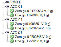
Confirm the input signal, which is the actual signal value the sensor is measuring. Press Save. Now EMGworks is ready to measure the output voltage when the sensor is put in this position. In this case, we need to put the X-axis of a Trigno accelerometer in a zero-g position, which can be achieved by sitting it on a flat, level surface. After doing this, press Start. When data collection is done, EMGworks computes the average signal value obtained and saves it. If there were too much variation in the signal, we would have automatically gotten a warning to that effect. Now, this calibration point has a check mark next to it in step 1 to show that the signal to voltage mapping has been measured. Repeat these steps for each point in the calibration. When that’s complete, every calibration point will have a check mark next to it, and click Next.